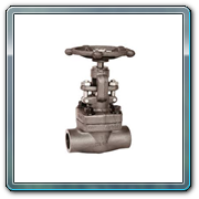
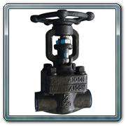
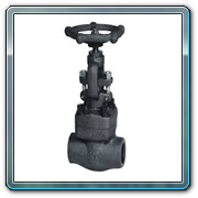
Gate & Globe Valves - Socket weld End..
A gate valve, also known as a sluice valve, is a valve that opens by lifting a round or rectangular gate/wedge out of the path of the fluid. The distinct feature of a gate valve is the sealing surfaces between the gate and seats are planar, so gate valves are often used when a straight-line flow of fluid and minimum restric¬tion is desired. The gate faces can form a wedge shape or they can be parallel. Gate valves are primarily used to permit or prevent the flow of liquids, but typical gate valves shouldn't be used for regulating flow, unless they are specifically designed for that purpose. Because of their ability to cut through liquids, gate valves are often used in the Petroleum industry.
A globe valve, different from ball valve, is a type of valve used for regulating flow in a pipe line, consisting of a movable disk-type element and a stationary ring seat in a generally spherical body.
Globe valves are named for their spherical body shape with the two halves of the body being separated by an internal baffle. This has an opening that forms a seat onto which a movable plug can be screwed in to close (or shut) the valve.
Special Features:
- Compact Design
- Maintenance free
- Bolted bonnet, solid wedge gate, outside screw and yoke with rising/non rising stem of gate valve, Plug type disc and outside screw and yoke are provided ease of operation
- Wedge – Ground and lapped to precision
- Gland – Self aligning type
- Integral satellite seat and backseat
Applications
- Cement & textile industry
- Fertilizer & chemical plants
- Petrochemical Industries & Refineries
- Steel plants
- Thermal, hydel and nuclear power plants
- Pulp & paper Industry
- Water & sewage treatment plants
- Food and beverage industries
- Pharmaceutical industry & Gas pipelines Etc.
Constructional Features
Body
The body is the main pressure containing structure of the valve and the most easily identified as it forms the mass of the valve. It contains all of the valve's internal parts that will come in contact with the substance being controlled by the valve. The bonnet is connected to the body and provides the containment of the fluid, gas, or slurry that is being controlled.
Bonnet
The bonnet provides a leak proof closure for the valve body. The threaded section of the stem goes through a hole with matching threads in the bonnet. Globe valves may have a screw-in, union, or bolted bonnet. Screw-in bonnet is the simplest bonnet, offering a durable, pressure-tight seal.
Wedge
The closure member of the valve, wedge are connected to the stem which is slid or screwed up or down to throttle the flow. Wedge is typically of the balance or unbalanced type. Unbalanced wedge are solid and are used with smaller valves or with low pressure drops across the valve. The advantages are simpler design, with one possible leak path at the seat and usually lower cost. Balanced plugs have holes through the plug. Advantages include easier shut off as the plug does not have to overcome static forces.
Stem
The stem serves as a connector from the actuator to the inside of the valve and transmits this actuation force. Stems are either smooth for actuator controlled valves or threaded for manual valves. The smooth stems are surrounded by packing material to prevent leaking material from the valve. This packing is a wearable material and will have to be replaced during maintenance.
Seat Ring
The seat ring provides a stable, uniform and replaceable shut off surface. Seat rings are usually held in place by pressure from the fastening of the bonnet to the top of the body. This pushes the cage down on the lip of the seat ring and holds it firmly to the body of the valve. Seat rings may also be threaded and screwed into a thread cut in the same area of the body
MATERIAL OF CONSTRUCTION |
||
| Body | : | CI / WCB / F.S / SS 304 / SS 316 |
| Internals | : | 13% Cr Steel, Gun metal / SS 304 /SS 316 |
| Actuator | : | Hand Wheel |
Technical Specification
Design and Manufacturing Standard
• API 602 / BS 5352
Testing Standard
• API 598 / BS 6755
Size range
• 15mm to 50mm (Class 800 & Class 150 )
Operation
• Manual hand Wheel
• Electrical and Pneumatic linear cylinder with accessories


